Posts

Export or Backup Azure Virtual Networks or Subnet information into CSV using PowerShell

 There may be times when you  want to get a report that contains information of all VNETS along with their subnets and address prefixes. You might have question, how to export or backup Azure VNET or subnets information into CSV.  This script will export Azure Virtual Network information along with subnets and address prefixes of all Active subscriptions into a CSV.

Automating a PowerShell Script using Azure Automation Account

So you have have created a PowerShell script to run a job quickly, but now you want to automate that PowerShell Script at a scheduled interval. For this you can use Azure Automation account where you can add you PowerShell script as a runbook and schedule that runbook at a desired time interval. In addition to the script that you have created, you also need to add some additional lines to make Automation account use a connection. Also note that if your script is performing some action (read or write) on any other subscription where the automation account is created, then you'll have to grant Automation Account's Runas account, the access of other subscriptions (You can refer the Microsoft article here. ) So, this is the PowerShell Script that you can use in your Automation Account Runbook.  $connectionName = "AzureRunAsConnection" try {     # Get the connection "AzureRunAsConnection "     $servicePrincipalConnection=Get-AutomationConnection -Name $connection...

Export or Backup Azure Network Security Groups into CSV using PowerShell

There could be many use cases where you may want to export Network Security Groups into CSV. You might have question, how to export or backup Azure Network Security Groups into CSV. Here is the PowerShell script that you can use to export Azure Network Security Groups into CSV using PowerShell script. This script will export Network Security Group along with rules of all Active subscriptions into a CSV.

Export or Backup Azure Route Table into CSV using PowerShell

Image
 There could be many use cases where you may want to export Azure route tables into CSV. Here is the PowerShell script that you can use to export Azure Route Tables into CSV using PowerShell script. This script will export Azure Route Tables along with routes of all Active subscriptions into a CSV.

F5 BigIP – Setting up Virtual Server with SSL offload

Image
 In this post we'll be setting up a VIP with a backend pool of three nodes. We have details of backend node IP addresses, which are given by developer team, and VIP address is allocated/secured by us. In our last post, we looked at F5 BigIP Initial Setup and Configuration . First thing first, so lets create an A record in DNS for application FQDN pointing to Virtual Server IP address. To start on F5 BigIP, we'll create Nodes. Navigate to Local Traffic >> Nodes >> Create New Node. Add the server name and Address value in the respective fields. After you add the all the backend nodes, you should be able to see the list of nodes in Nodes section Next step is to create Pools of backend nodes. Navigate to Local Traffic >> Pools >> Create New Pool. Add the Name of the pool, and add backend nodes to the pool that we added in in last step along with port and protocol. Also add the health monitor to be used to monitor the health of backend nodes, so that inactive...

F5 BigIP Initial Setup and Configuration

Image
 In this blog post we'll setup and configure a standalone F5 Application Delivery Controller (commonly referred as load balancer). We'll be using a BigIP VM appliance for this lab. Before we begin, we should have following information handy. BIG-IP base registration key Internal/External self IP address, netmask, and default gateway IP address on the management route 1.      After deploying the ova file, when we startup the appliance, we'll be prompted to configure management connectivity. After which we can access the GUI of BigIP using https://<management_IP_address> and default username and password as admin/admin. After login, management IP configuration and admin/root credentials can be updated 2.      Next step is to activate Base registration /add-on license keys  3.     Next step is to enable the modules out of licensed ones, that we want to use. 4.     Its time to configure network settings now. We'll be set...

Ansible-Playbook to display output of multiple show commands (using stdout_lines with Loop)

 In this playbook, we we'll see how we can get display of multiple show commands in stdout_lines format. We can make use of loops (or with_items) for submitting multiple commands, but debug output with stdout_lines does not gives the formatted result as it would give for single command. So in case of multiple commands, we can debug the output of each command separately in stdout_lines format. #Ansible-Playbook to display Output of multiple show commands - name: Display Output of multiple show commands   hosts: all   gather_facts: no   connection: network_cli   become: no   become_method: enable   tasks:    - name: Get the config      cli_command:       command: "{{ item }}"      register: result      with_items:        - show ip access-lists TestACL-1 | include 150        - show ip access-lists TestACL-2 | include 250       ...

DNS Terminologies and Definitions

Image
DNS terminology is complex and confusing, so much so that not just one, but two RFC's have been written just trying to clear up what each term means (RFC 8499 and RFC 7719). Below are the terms: 1. FQDN - FQDN stands for Fully Qualified Domain Name, which is the complete domain name for a host on the Internet. The FQDN has two parts: the hostname, and the domain name. e.g. in foo.example.com, foo is the hostname, and example.com is the domain name. 2. Client / Stub Resolver : A DNS client asks simple questions like: what is the IPv4 address of www.google.com? It is unable to follow referrals given by other name servers to track down answers on its own and has to rely on a full-fledged DNS server to chase down the answer. The term "stub resolver" refers to the piece of software code that sends the simple DNS question, usually built-in as part of Operating System. For example, systems such as Windows and Linux come with build-in stub resolvers that provide name lookup for a...

Map Microsoft Azure and AWS services to Google Cloud Products

If you have already worked on Azure Cloud or AWS and now you are moving or expanding your cloud to Google, then you might want to see what the former cloud service providers' services translate to in Google Cloud. So here you can get the answer. Map Microsoft Azure services to Google Cloud Products https://cloud.google.com/docs/compare/azure#service_comparisons Map  AWS services to Google Cloud Products https://cloud.google.com/docs/compare/aws#service_comparisons

Understanding VMware NSX Control Plane

In this post we'll discuss about NSX control plane in detail. I'll describe the  NSX controllers and functions along with NSX Controller workload distribution. We'll also identify the user world agent in the control plane and the control plane component interactions.

Transport Zone and Transport Node in VMware NSX-T

Image
Transport Zones A transport zone controls which hosts a logical switch can reach. It can span one or more host clusters also known as transport nodes. If two transport nodes are in the same transport zone, VMs hosted on those transport nodes can be attached to the NSX logical switch segments that are also in that transport zone. If VMs are attached to switches that are in different transport zones, the VMs cannot communicate with each other.

Azure PowerShell Commands for Listing Network Configuration

While working on Azure, PowerShell can be your friend when you need some information quickly, live and that is not visible in Azure Portal. Following are few of the commands that can be helpful for a network administrator working on Azure. List all virtual network subnets by using PowerShell Get-AzureRmVirtualNetwork -Name <My-vnet-name> -ResourceGroupName <vnet-resource-group-name> | Get-AzureRmVirtualNetworkSubnetConfig | Format-Table List detailed route table of an ExpressRoute circuit. This command output will include prefixes learnt/advertised with Next hop, Local Preference, Weight and AS Path list. Get-AzureRmExpressRouteCircuitRouteTable -ResourceGroupName: <express-route-resource-group-name> -ExpressRouteCircuitName: <express-route-circuit-name> -PeeringType: AzurePrivatePeering -DevicePath: Primary | Format-Table  List summary of BGP neighbor information for a particular routing context. This information is useful to determine for how long a r...

Azure ExpressRoute Physical and Logical Topology

Image
If you are asked to explain physical and logical connectivity of Azure Express Route circuit by looking into the portal, It might be little confusing, if you are not familiar with Azure Portal. So here is the network diagram showing physical and logical connectivity of Express Route setup.  A single express Route Direct circuit has built-in redundancy with two links, that extends from On-Premise with redundant routers to Azure Cloud with redundant Virtual Network Gateways, through redundant routers in Connectivity Partner Location.  ExpressRoute Direct Connectivity diagram Customer compute device (for example, a server or PC) CEs: Customer edge routers PEs (CE facing): Provider edge routers/switches that are facing customer edge routers. Referred to as PE-CEs in this document. PEs (MSEE facing): Provider edge routers/switches that are facing MSEEs. Referred to as PE-MSEEs in this document. MSEEs: Microsoft Enterprise Edge (MSEE) ExpressRoute routers Virtual Network (VNet) Gate...

Ansible Playbook for Network OS Upgrade with pre and post checks

You have 100s of network switches or routers that you need to upgrade. How much time would it take for you to do the upgrades? There are a lot number of sub-tasks involved while upgrading IOS image of a Cisco router or a switch. This time of upgradation can be reduced through automation from various Enterprise Configuration Management tools that also have ability to upgrade network OS. Though these tools give an easy to use graphical interface, but this requires you to have appropriate license and also restricts you to customize your upgrade process. Ansible is one of the tool that can be used and the upgrade process can also be customized to include any tasks that you want, e.g. taking pre-checks, post-checks and then comparing them and highlighting the differences, etc.

Ansible to Configure DHCP IP-Helper Address on Multiple Devices

In this post we'll be configuring ip-helper address on multiple devices using Ansible. We'll be defining the interfaces to be configured for different devices in host_vars. In ansible, host-specific variables can be defined in the host_vars sub-directory either in the home directory of user executing ansible play or in /etc/ansible. Each file/directory in the host_vars sub-directory is name after the host it represents, e.g. host variable for device router-01 are stored in either ~/host_vars/router-01 or /etc/ansible/host_vars/router-01

VMware NSX Logical Routing

In this post we will discuss the current challenges with data center routing and the evolution of router placement. Current Challenges in Data Center Routing Current data centers are an agglomeration of several generations of networking and security products. Today's data center networking team faces significant challenges: Manual, complex provisioning of hardware devices and agents Limited placement, mobility, and efficiency due to silos VLAN sprawl, firewall rule sprawl, and static IP inflexibility Several networking and security blind spots Performance choke points due to traffic hairpinning Lack of seamless, instant integration with cloud management platforms and applications

Interface Tracking to Remove Static Route from Routing Table

In this blog post we'll see how to monitor an interface for its status based on which a static route can be tracked. The static route will be removed from routing table when the interface goes down Create tracking object RTR#conf t RTR(config-track)# track 10 interface loopback 101 line-protocol RTR(config-track)# delay down 5 up 10 RTR(config-track)# exit

VMware NSX Traffic Flow — East-West & North-South

Image
Understanding how traffic is flowing in NSX environment is an important aspect to successfully maintain and troubleshoot networks having NSX. In this post we'll understand hop-by-hop flow of traffic in East-West and North-South directions. East-West: VMs on Same Subnet, Same Host VM-1 has IP address 172.16.20.6 and VM-2 has IP address 172.16.20.7 VM-1 vNIC è Logical Switch (Segment ID 5002) è VM-2 vNIC

NSX-T Architecture | Overview of NSX-T Management, Control, and Data Plane

Image
NSX-T Manager NSX-T utilizes a multi-tiered networking stack. The NSX Management Cluster is a 3 node high availability cluster. The cluster consists of a converged Management (Policy) & Control Plane cluster services. The NSX management nodes each contain a Management plane, a central control plane, a policy role and a replicated desired state datastore. The NSX Management Cluster provides availability of all management services and increased performance. The converged appliance allows for easier operations with less systems to monitor and maintain.

VMware NSX Data Plane — Components & their interaction

In this post we'll discuss about the NSX data plane, it's components and how these data plane components interact with each other.

VMware NSX Management Plane — Components & their interaction

Image
In this post, we'll discuss about NSX Management plane in detail. We'll also Identify the user world agent in the management plane and management plane component interactions.

VMware NSX Architecture, NSX Planes and Components

Understanding the architecture of NSX platform is imperative to continue successful operation of NSX. NSX Operates on a variety of planes and those planes are occupied by various components. Knowledge of those components and on which plane they operate is a key to the deployment, configuration, operational management, and troubleshooting NSX. In this post we'll be discussing about NSX architecture, various planes of NSX operations and various component in each plane.

Introduction to VMware NSX - Use Cases and Key Features

Image
In this post we'll be discussing about NSX, including it's use cases and key features, which will help us to make informed decisions about our design, deployment, configuration and continued successful operation of NSX. Automation Use Cases Automating IT: Automation allows for quick, secure and automatic deployment of applications and services Developer Cloud: Automation enables developers to use a unified API for on-demand networking and security services. Multi-tenant Infrastructure: Automation empowers organizations to provision and deliver networking and security services to multiple tenants on a shared infrastructure Security Use Cases VMware NSX embeds security functions right in the hypervisor. It delivers micro-segmentation and detailed security to the individual workload, enabling a fundamentally more secure data center. Security policies travel with the workloads, independently of where workloads are in the network topology. Micro-Segmentation: NSX...

How to Configure Infoblox DDI Grid and Create DNS Records

Image
In this video, we'll accomplish and demonstrate following tasks Deploy NIOS OVA in VMware Workstation Configure IP address in the deployed Infoblox VM Add temporary license in Infoblox Setup a DDI Grid and add a new member to it Enable DNS and DHCP services in DDI grid Create a Zone, Name Server and an A record

How to Install VMware Tools on CentOS Linux

Image
Here you can see how to install VMware tools on a CentOS Linux VM. 1. Navigate to VM  >>  Install/Reinstall VMware Tools...

[Video] How to create Microsoft Azure Account for Free.!! Deploy your first VM and avail services for a year

Image
This video demonstrates to sign up for Free Tier Microsoft Azure account and deploy a Windows 10 virtual machine that can be access from anywhere in the world. We will talk about signup process, selecting the right VM size based on our requirements, deploying the VM and then finally accessing the VM through RDP.

[Video] How to Run Cisco IOU in GNS3 VM?

Image
This video show how to download and configure GNS3 VM for running Cisco IOU images. This also includes downloading and installing GN3 appliances form GNS3 marketplace to run Cisco IOS Over Unix.

[Video] Fetch Network Inventory from Ansible | Get Serial & model number and OS version of network devices

Image
Fetch Network inventory using Ansible. Depending upon what information we need, we can include the parameters in ansible-playbook. Using Ansible will really save time to accomplish many tasks that required to be performed on bulk devices.

[Video] Install Ansible and run your first playbook

Image
Are you a network engineer and want to know from where to start network automation? Or want to learn how to install and configure Ansible server for running your first ansible-playbook on Ansible.   Updating Yum # yum -y update Install Python #sudo yum install python3 Install Ansible # sudo pip3 install ansible Install paramiko sudo pip3 install paramiko Verify the status/version of installed components pip --version python --version ansible --version

RSA key save Error Resolution in Ansible

If you are also struggling while running ansible-plabook for new hosts and getting error like following, then you have two options. Either connect to each host one by one to save the RSA keys of that host to your ansible server or you can disable host key checking in ansible configuration file. Here is the way to do it Edit/create either of the following files  /etc/ansible/ansible.cfg or ~/.ansible.cfg and add the following to the file. [defaults] host_key_checking = False Error Message before disabling host key checking fatal: [ios-xe-02]: FAILED! => {"ansible_facts": {"discovered_interpreter_python": "/usr/libexec/platform-python"}, "changed": false, "msg": "paramiko: The authenticity of host '[ios-xe-02]:8181' can't be established.\nThe ssh-rsa key fingerprint is b'b7e974a8cbf96d464f7be3e12a86d265'."}

Ansible - Network Debug and Troubleshooting

There may be some times when you are trying to run an ansible-playbook that you created but getting errors that you are not able to understand. To understand why ansible-playbook is not working, we can enable debugging and logging to understand what is going wrong. Following are the steps to enable logging in ansible. Before running ansible-playbook run the following commands to enable logging: # Specify the location for the log file export ANSIBLE_LOG_PATH=~/ansible.log # Enable Debug export ANSIBLE_DEBUG=True # Run with 4*v for connection level verbosity ansible-playbook -vvvv ... After Ansible has finished running you can inspect the log file which has been created on the ansible-controller: less $ANSIBLE_LOG_PATH 2017-03-30 13:19:52,740 p=28990 u=fred |  creating new control socket for host veos01:22 as user admin 2017-03-30 13:19:52,741 p=28990 u=fred |  control socket path is /home/fred/.ansible/pc/ca5960d27a 2017-03-30 13:19:52,741 p=28990 u=...

Get Model Number and Serial number of Cisco devices using ios_facts module

 This ansible-playbook will get the model number and serial number of Cisco devices using ios_facts module --- - name: Define Parameters   hosts: XE   gather_facts: no   connection: network_cli   tasks:    - name: Get the facts      ios_facts:        gather_subset: all    - name: Display model and serial number      debug:        msg: "Model number of {{ ansible_net_hostname }} is {{ ansible_net_model }} and serial number is {{ ansible_net_serialnum }}" ~ ~ https://docs.ansible.com/ansible/latest/modules/ios_facts_module.html

Adding and Editing ACL on Cisco IOS using Ansible

Ansible playbook for adding a new ACL to Cisco IOS devices. --- - name: Define Paramenters   hosts: XE   connection: network_cli   tasks:     - name: load new acl into device       ios_config:         lines:           - 10 permit ip host 192.0.2.1 any log           - 20 permit ip host 192.0.2.2 any log           - 30 permit ip host 192.0.2.3 any log           - 40 permit ip host 192.0.2.4 any log           - 50 permit ip host 192.0.2.5 any log           - 60 permit ip host 192.0.2.6 any log         parents: ip access-list extended test         before: no ...

Specifying SSH port in Ansible Inventory

There may be some instances where you set a custom port for SSH on your network device. If ssh port for hosts is different than the default port 22, it can be specified in the inventory file with colon (:) after hostname. #vi inventory   # Inventory file for Ansible   [XE] ios-xe-mgmt.cisco.com:8181 ios-xe-mgmt-latest.cisco.com:8181   [XR] sbx-iosxr-mgmt.cisco.com:8181

Configure interfaces with Ansible

 Today we will be configuring network devices from Ansible using ios_config module. Ansible playbook to create loopback interfaces and add description ---   - name: Define Parameters   hosts: XE   gather_facts: no   connection: network_cli   tasks:     - name: Create loopback interfaces       ios_config:         lines:           - description loopback interface by prashant         parents: "{{ item }}"       with_items:           - interface loopback 25           - interface loopback 30           - interface loopback 35

Ansible-playbook for backing up running config of Cisco IOS

This ansible-playbook can be used to backup running configuration from Cisco IOS devices. You can refer to my earlier post Getting Started with your first ansible-playbook for Network Automation  to know about the parameters used in this playbook. Inventory file # Inventory file for Ansible [XE] ios-xe-mgmt.cisco.com:8181 ios-xe-mgmt-latest.cisco.com:8181 [XR] sbx-iosxr-mgmt.cisco.com:8181 [all:vars] ansible_network_os=ios Playbook --- - name: Define Parameters   hosts: XE   gather_facts: no   connection: network_cli   tasks:    - name: backup the config      ios_config:       backup: yes      register: backup_config    - name: Store the config to directory      copy:       src: "{{ backup_config.backup_path }}"       dest: "/tmp/backups/{{ inventory_hostname }}"

LAN Security - Threats and Prevention

MAC Flooding and Spoofing Attacks MAC Flooding:  In a typical MAC flooding attack, a switch is fed many Ethernet frames, each containing different source MAC addresses, by the attacker. The intention is to consume the limited memory set aside in the switch to store the MAC address table. Once the mac address table is full with the spurious mac addresses, the switch will start to broadcast the frames including for the genuine MAC address if it has no entry for the destination MAC address in it's Mac address table. After launching a successful MAC flooding attack, a malicious user could then use a packet analyzer to capture sensitive data being transmitted between other computers.  MAC Spoofing:  A MAC spoofing attack consists of generating a frame from a malicious host borrowing a legitimate source MAC address already in use on the VLAN. This causes the switch to forward frames out the incorrect port. The switch updates its mac-address-table based on t...

Getting Started with your first Ansible Playbook for Network Automation

Installing Ansible and related components Updating Yum # sudo yum -y update Install python3-pip # sudo yum install python3-pip Install/upgrade ansible to latest version # sudo pip3 install ansible Install/upgrade ansible to latest version # sudo pip3 install paramiko Verify the status/version of tools installed pip3 --version python3 --version ansible --version Install and c heck version of ansible installed [developer@devbox Network_Support]$ansible --version ansible 2.7.8   config file = /home/developer/Network_Support/ansible.cfg   configured module search path = ['/home/developer/.ansible/plugins/modules', '/usr/share/ansible/plugins/modules']   ansible python module location = /usr/local/lib/python3.6/site-packages/ansible   executable location = /usr/local/bin/ansible   python version = 3.6.5 (default, Jul 19 2018, 10:49:52) [GCC 4.8.5 20150623 (Red Hat 4.8.5-28)] Create inventory file ...

Spanning Tree Protocol Operation

Image
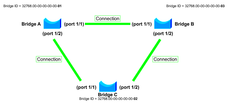
Whenever there is redundancy in the network, there are chances of formation of loops. When loops are at layer 3, TTL value in the packet header saves the packet from looping endlessly. Similarly, to avoid loops at layer 2, Spanning Tree Protocol (STP) comes into play. STP exchanges BPDU messages with other switches to detect loops, and then removes the loop by shutting down selected bridge interfaces. This algorithm guarantees that there is only one active path between two network devices. A layer 2 network with redundancy without STP can cause following issues: Broadcast Storm Unstable mac-address table in a switch Duplicate frames arriving at host STP Operation Election of Root Bridge With STP, the key is for all the switches in the network to elect a root bridge that becomes the focal point in the network. All other decisions in the network, such as which port to block and which port to put in forwarding mode, are made from the perspective of this root bridge. Each ...

Basic Datacenter Design with Redundancy (Colocation Datacenter)

Image
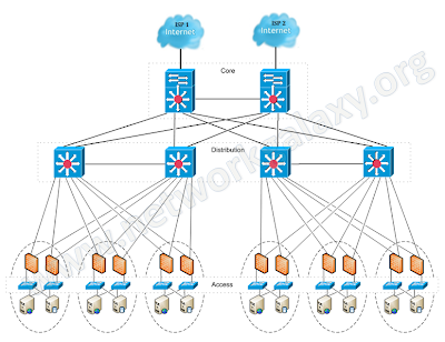
The very basic thing that an organization expects while designing its network is maximum uptime, and this maximum uptime can only be achieved when there is redundancy in the network. So in this article, we'll design a network for a company hosted in a datacenter with redundant devices and links. NOTE: The configuration of devices in this article does not include configuration for securing the control-plane of core or aggregation routers. Full Network topology:

Stacked Switches

Image
A stackable switch is a network switch that is fully functional operating standalone but which can also be set up to operate together with one or more other network switches, with this group of switches showing the characteristics of a single switch but having the port capacity of the sum of the combined switches. Following are some of the benefits of stacked switches. 1. Simplified Network Management Multiple physical switches in a stack appear as a single logical switch. This eases management overhead because there are fewer devices in the network to manage. A single IP address is used to manage the logical switch. All manageable entities (for example, Ethernet interfaces and VLANs) on all physical switches can be configured and managed from the logical switch. The logical switch will appear as a single entity in the network. In a Layer 2 network, the logical switch will appear as a single spanning-tree entity.

Creating MPLS Layer 3 VPN

Image
When used with MPLS, the VPN feature allows several sites to interconnect transparently through a service provider's network. One service provider network can support several different IP VPNs. Each of these appears to its users as a private network, separate from all other networks. Within a VPN, each site can send IP packets to any other site in the same VPN. Each VPN is associated with one or more VPN routing and forwarding instances (VRFs). A VRF consists of an IP routing table, a derived Cisco express forwarding (CEF) table, and a set of interfaces that use this forwarding table. The router maintains a separate routing and CEF table for each VRF. This prevents information being sent outside the VPN and allows the same subnet to be used in several VPNs without causing duplicate IP address problems. In this document, we'll be configuring basic MPLS Layer 3 VPN for two customers, each having two physical sites at different location. Network Topology: ...

Traffic Flow Decisions in MPLS Network

Image
In this article, we will study how forwarding decisions are made in a MPLS Network. You can check out the configuration of the network at Creating Layer 3 MPLS VPN . Network Topology:

Managing Standby Unit from the Terminal of Primary Firewall when they are in HA

Fortigate execute ha manage 0 where the 0 is serial no of the secondary device. execute ha manage <id>    please input peer box index. <0>     Subsidary unit FGT80C3912608121 NINMUM03-DB-PRI-~ # execute ha manage <id>    please input peer box index. <0>     Subsidary unit FGT80C3912608121 Cisco

Fortigate Backup VPN

You can configure a route-based VPN that acts as a backup facility to another VPN. It is used only while your main VPN is out of service. This is desirable when the redundant VPN uses a more expensive facility. You can configure a backup IPsec interface only in the CLI. The backup feature works only on interfaces with static addresses that have dead peer detection enabled. The monitor option creates a backup VPN for the specified phase 1 configuration. Redundant tunnels do not support Tunnel Mode or Manual Keys. You must use Interface Mode.

Cisco ASA 9.0 Network Address Translation

http://www.cisco.com/en/US/docs/security/asa/asa90/configuration/guide/nat_overview.html http://www.cisco.com/en/US/docs/security/asa/asa90/configuration/guide/asa_90_cli_config.html http://www.pcausa.com/Utilities/pcattcp.htm

Cisco ASA Active/Active Failover Configuration

Image
Active/Active failover is only available to security appliances in multiple context mode. In an Active/Active failover configuration, both security appliances can pass network traffic. In Active/Active failover, you divide the security contexts on the security appliance into failover groups. A failover group is simply a logical group of one or more security contexts. You can create a maximum of two failover groups on the security appliance. The admin context is always a member of failover group 1. Any unassigned security contexts are also members of failover group 1 by default. We have already seen the configuration for Active/Standby failover in the previous article. This article focuses on how to configure an Active/Active Failover configuration on ASA Security Appliance. Network Diagram  (Physical Topology)

Cisco IOS Archiving for Configuration Backup

Configuration backup is an important part of network administration. When there are multiple nodes (routers/switches) in a network, some kind of automation is needed to take regular backups. Apart from third party applications like rancid  (free) and Kiwi CatTools  (free/paid), you can use Cisco's IOS archiving feature for regular configuration backups. In this article, we'll configure a Cisco router to send configuration backup to a FTP server. First we need to configure the FTP parameters, so that router can authenticate to FTP server. Router1(config)# ip ftp username ftpuser Router1(config)# ip ftp password ftppass

Virtual Firewalls (Contexts)

Image
Scenario: You have worked as a network engineer for many companies, but now you have started your own collocated datacenter. At the starting, due to budget constraints, you want to be smart and decided to share a single physical firewall (Cisco ASA) between two customers i.e. Customer-A and Customer-B. Objectives: Both customers should feel that they have a separate Firewall for them. None of the Customers should be able to manage others firewall policies. Customer-A has opted for Silver plan, so allocate the resources accordingly. Customer-B has opted for Gold plan, so allocate the resources as per plan. Physical Topology

GNS3 Configuration For Running Cisco ASA

Settings for running a Cisco ASA 8.0(2) Identifier Name: ASA802 RAM: 256 MiB Qemu Options: -hdachs 980,16,32 -vnc :1 Initrd: asa802-k8.initrd.gz Kernel: asa802-k8.kernel Kernel Cmd Line: console=ttyS0,9600n8 bigphysarea=16384 auto nousb ide1=noprobe hda=980,16,32