
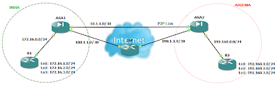
Azure ExpressRoute Physical and Logical Topology
If you are asked to explain physical and logical connectivity of Azure Express Route circuit by looking into the portal, It might be little confusing, if you are not familiar with Azure Portal. So here is the network diagram showing physical and logical connectivity of Express Route setup.
A single express Route Direct circuit has built-in redundancy with two links, that extends from On-Premise with redundant routers to Azure Cloud with redundant Virtual Network Gateways, through redundant routers in Connectivity Partner Location.
 |
| ExpressRoute Direct Connectivity diagram |

- Customer compute device (for example, a server or PC)
- CEs: Customer edge routers
- PEs (CE facing): Provider edge routers/switches that are facing customer edge routers. Referred to as PE-CEs in this document.
- PEs (MSEE facing): Provider edge routers/switches that are facing MSEEs. Referred to as PE-MSEEs in this document.
- MSEEs: Microsoft Enterprise Edge (MSEE) ExpressRoute routers
- Virtual Network (VNet) Gateway
- Compute device on the Azure VNet
Comments
Post a Comment